Mechanical Summary
Botsley's body was constructed from laser-cut MDF (medium-density fiberboard). We chose MDF as a prototyping-friendly material, and it saw us through many mechanical iterations. In his final embodiment, Botsley looks very simliar to a stylish retro TV set on wheels, with a laser-rasterized piece of acrylic edge-lit red or blue to identify his team.
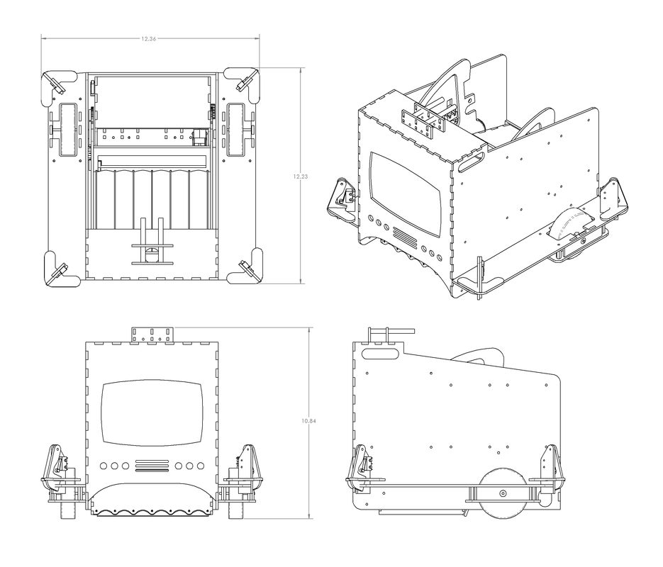
Botsley's overall dimensions are as follows. He was designed to fit within the size envelope requirement of a rectangular prism no larger than one cubic foot (1728 cubic inches), and fit successfully at about 12.4" x 12.4" x 11" = 1691 cubic inches, excluding his stylish antennae.
Botsley's overall dimensions are as follows. He was designed to fit within the size envelope requirement of a rectangular prism no larger than one cubic foot (1728 cubic inches), and fit successfully at about 12.4" x 12.4" x 11" = 1691 cubic inches, excluding his stylish antennae.
Chassis
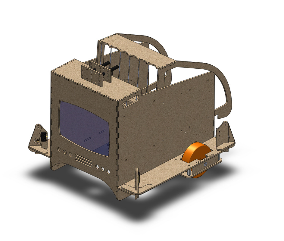
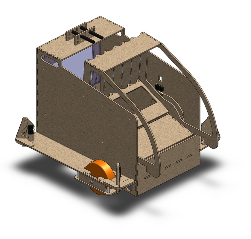
Shelves on either side of Botsley provided room for electronics.
| 
Maxon motors drove Botsley's wheels directly through spider couplers.
|
In the final iteration, we replaced the bottomless box we'd been working with earlier with a U-shaped chassis plate and eliminated the timing belts we'd been using in earlier versions. This had the advantage of fewer parts that could give us trouble, but unfortunately limited our top speed as we sacrificed the 40:25 pulley ratio we'd had with the timing belt.
Botsley's drive train was powered by two Maxon motors with encoders connecting to two Banebot rubber wheels through SPDL-stocked spider couplers. We implemented a Proportional-Integral control loop to adjust the PWM voltage going to the motors, to ensure the motors would run at consistent speeds. See the Electronics page for details about driving the motors.
All of the circuit boards on Botsley, and his 4 batteries were mounted in the available space on either side of his central body above the 'fender' area. Botsley made use of 4 bumper switches in his four corners to help him navigate. A collision with any bumper triggered a simple limit switch.
Collecting and Depositing Ping Pong Balls
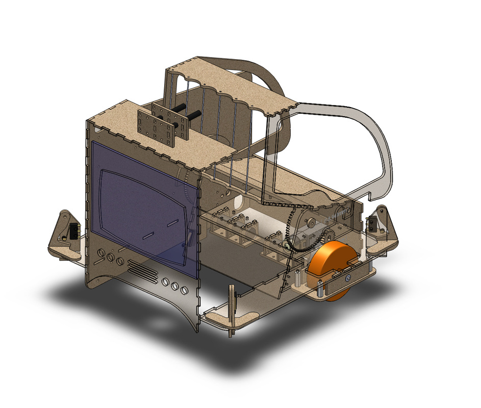
The final embodiment of Botsley's hopper/dump system.
Early on in the design process, the team prototyped several methods of picking up ping-pong balls. Our goals were simplicity, speed and effectiveness. We hoped to develop a system that would run while we the robot drove around so that the other systems didn't have to think about picking up ping pong balls.
We chose a 'hopper' design, similar to what's used to quickly pick up tennis balls. We originally were going to run this hopper on a crank shaft or four-bar linkage to deposit balls in a bin with a controllable gate.
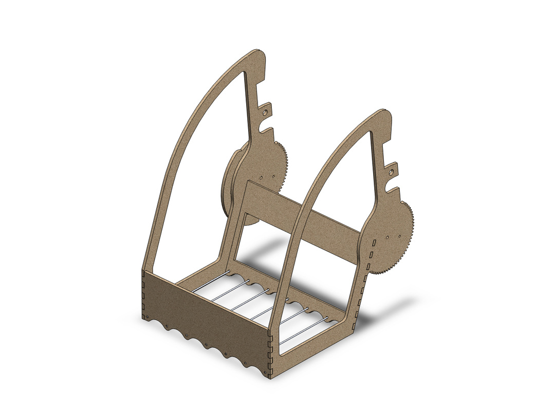
After some CAD experimentation we managed to come up with a design that allowed for a single degree of freedom system to pick up balls and dump.
In its final implementation, the hopper was fairly shallow from front to back, but an internal cow-catcher kept the hopper from missing balls. This short distance kept the moment arm low enough to drive the hopper with a single SolarBotics DC gear motor a 5V, turning a pilot spur gear which moved the hopper at a 1:4 ratio. We hollowed out the sides of the hopper as shown and lined them with paper, also to reduce weight.
The hopper's range of motion was governed by 3 limit switches, triggered by the piece of MDF on the far side of the render above. They let the bot know when the hopper was on the floor, when it was up, and when it had reached its far limit for dumping.
One design feature that went untested was the incorporation of two hooks on the hopper: when it dumps, the rectangular cavities are intend to 'lock on' to the playing field wall to prevent other 'bots from sumo-ing our 'bot off of its bin.
We chose a 'hopper' design, similar to what's used to quickly pick up tennis balls. We originally were going to run this hopper on a crank shaft or four-bar linkage to deposit balls in a bin with a controllable gate.
After some CAD experimentation we managed to come up with a design that allowed for a single degree of freedom system to pick up balls and dump.
In its final implementation, the hopper was fairly shallow from front to back, but an internal cow-catcher kept the hopper from missing balls. This short distance kept the moment arm low enough to drive the hopper with a single SolarBotics DC gear motor a 5V, turning a pilot spur gear which moved the hopper at a 1:4 ratio. We hollowed out the sides of the hopper as shown and lined them with paper, also to reduce weight.
The hopper's range of motion was governed by 3 limit switches, triggered by the piece of MDF on the far side of the render above. They let the bot know when the hopper was on the floor, when it was up, and when it had reached its far limit for dumping.
One design feature that went untested was the incorporation of two hooks on the hopper: when it dumps, the rectangular cavities are intend to 'lock on' to the playing field wall to prevent other 'bots from sumo-ing our 'bot off of its bin.
Sensing IR Beacons
Botsley in dumping state. Note the rear-facing IR beacons and hopper limit switches.
One of our initial ideas was to use two IR phototransistors mounted on a turret driven by a stepper motor. The goal was to find and track any beacon, and always know the direction of the best bin to dump and defend.
Two stepper motors, three turrets, and hundred of lines of code later, we abandoned the idea because, due to the vibration of the turret, we couldn't reliably see and keep a lock on the beacons and there were bigger fish to fry. We re-appropriated one of our spare motor mounts and switched a rear-sensing fixed solution. Now, when it's time to dump, our 'bot turns around until it sees a bin on its side, then backs up into that bin, using limit switches to guide it before it dumps. If it loses the bin on the way, it turns until it sees the bin again.
Two stepper motors, three turrets, and hundred of lines of code later, we abandoned the idea because, due to the vibration of the turret, we couldn't reliably see and keep a lock on the beacons and there were bigger fish to fry. We re-appropriated one of our spare motor mounts and switched a rear-sensing fixed solution. Now, when it's time to dump, our 'bot turns around until it sees a bin on its side, then backs up into that bin, using limit switches to guide it before it dumps. If it loses the bin on the way, it turns until it sees the bin again.
