E128 and Power Board
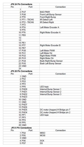
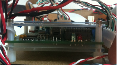
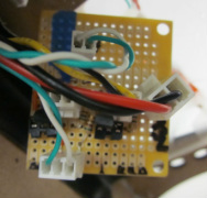
The brains of Botsley was driven by the 9S12E128 (E128) microprocessor. The microprocessor was connected to a soldered prototype board which contained all of the input and output connections to the separate module board for each subsystem.
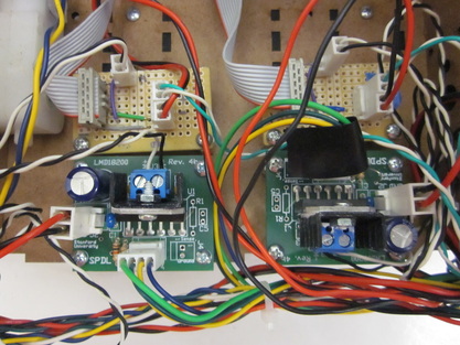
Botsley gets power from four 7V, rechargeable battery packs. Three packs are linked in series to output 21V in order to drive the Maxon motors. This source was then regulated down to 14V for the LED circuit that identifies Botsley's team and to 5V to power the DC motor controlling the movement of the hopper. The fourth battery is regulated down to 5V, which powers the logic signals sent between the E128
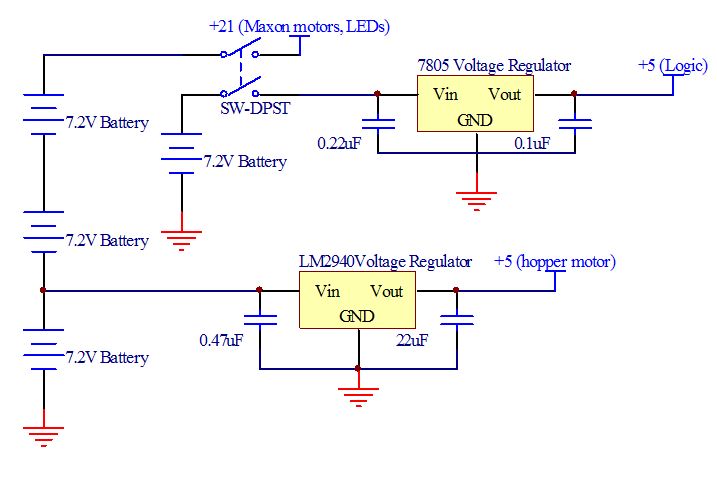
Power Supply Board
| 
|
Wireless Controller
Throughout the game Botsley receives information from the Field Status Reporter that tells him when the game starts, how many balls are in each bin, and the angle at which the wall is rotating. Botsley uses this information at the beginning of the game to identify his team and during the game to identify a bin to deposit the balls.
Actuators
Drive Train Motors
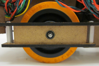
The drive train that propels Botsley around the field consists of two Maxon DC motors that were controlled with a 30KHz? PWM signal. These motors are in a direct drive configuration, using spider couplers to connect the motors to the wheel axles. The motors have a built in (gear ratio) gearbox and encoders, which our team used to implement PI control. Utilizing this feedback to the E128, we were able to get Botsley driving straight as he moved about the field.
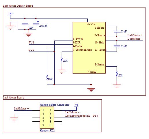
Maxon Motor Board
| 
|
Hopper Motor
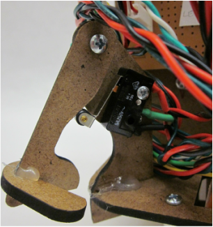
The hopper, which picks up ball using a tennis hopper motion, is animated by a geared down Solarbotics GM9 DC motor driven by two half-bridges on a L293NE. It's position is defined by three internally mounted limit switches that bound the "hopper down" and "hopper up" positions as Botsley is collecting ping pong balls, and "hopper dump" as Botsley deposits ping pong ball into a bin. The circuit used for the limit switches are the same as those used for the external bump sensors which are explained below.
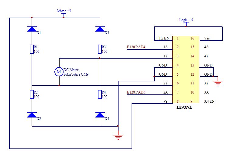
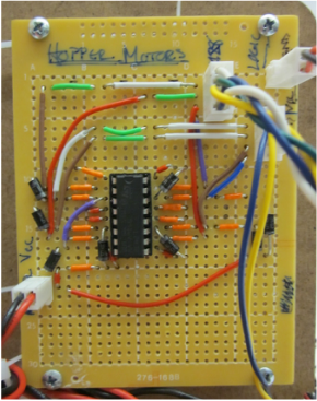
Hopper DC Motor Board
| 
|
Sensors
Photosensors
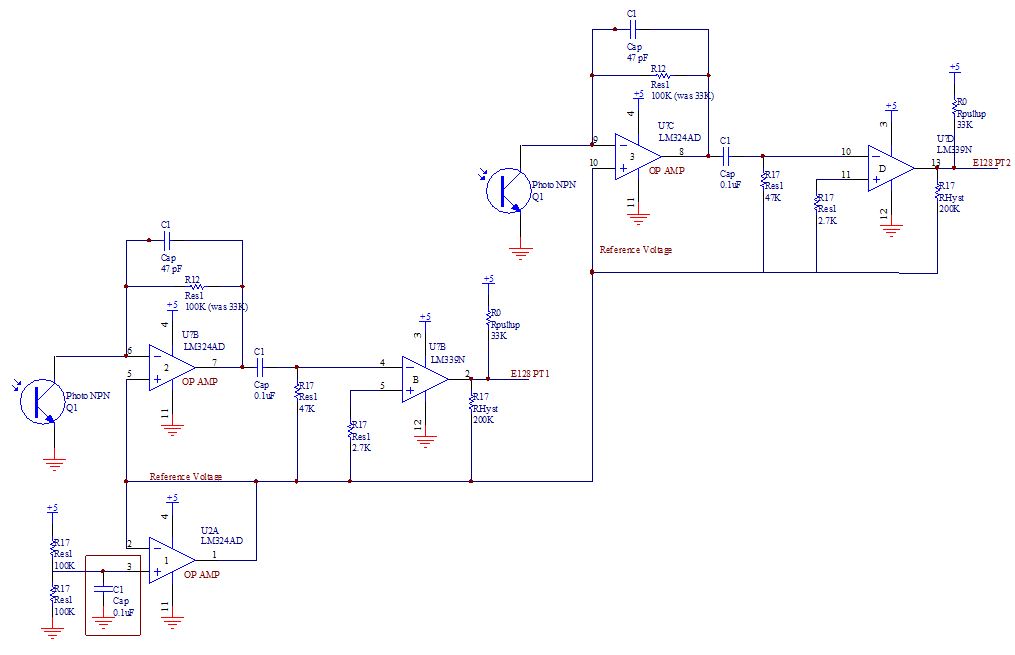
Two infrared phototransistors, mounted on top of Botsley, read in infrared signals coming from a beacon array at each bin location on the field. Each bin emits a different frequency which allows Botsley to see and target certain bins at various points in the game. This information is used at the beginning of the game to identify the team color, red or blue and during the game as Botsley targets a bin to deposit balls into. A high pass filter was using between the op amp and comparator to filter ambient light at 33Hz. A hysteresis band was also used on the comparator circuit to ensure a clean and noise free signal.
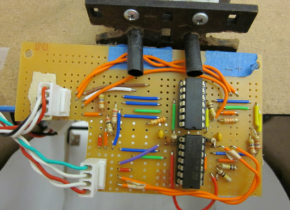
Beacon Board
| 
|
Bump Sensors
In addition to the internal limit switches of the hopper mechanism, four limit switches were used as external bump sensors on Botsley's outer four corners to detect when a wall was being hit. A single pull, double throw switch was used in each of these instances and is powered through the E128.
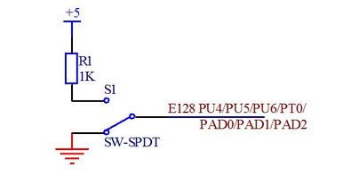
Sample of our several limit switch circuits
| 
|
Team Identification
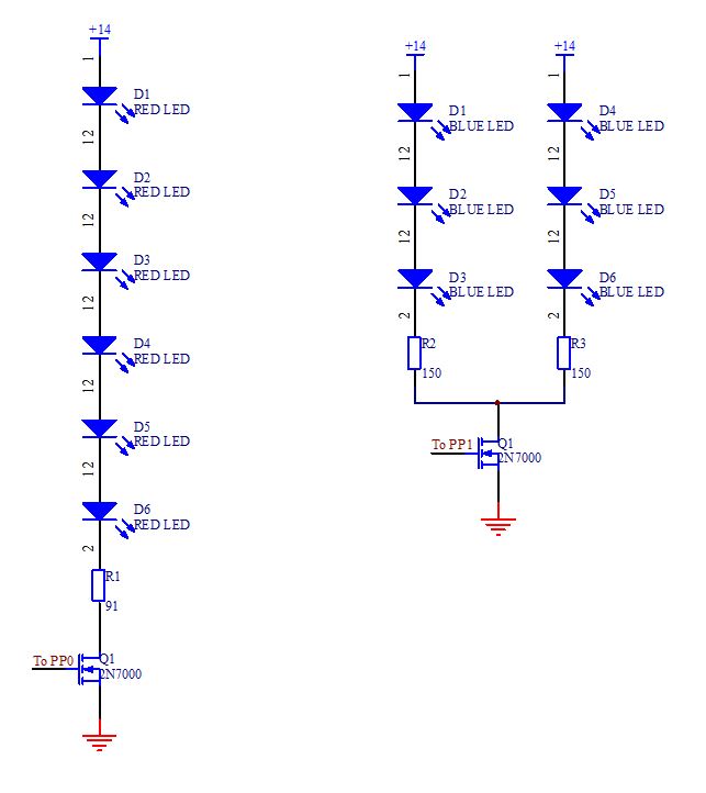
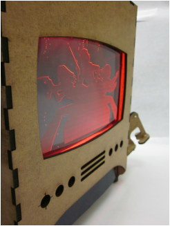
Botsley displays his team by turning on either a red or blue string of LEDs that light up a Charlie's Angels graphic displayed on his front panel 'TV screen.' We rastered the logo into acrylic and lit it from above via LEDs placed in edge-drilled holes.
The red COM-0959 LEDs from Sparkfun have a forward voltage of 2.0V and rated for 20mA of current, although the suggested running current is 16-18mA. A daisy chain of six red LEDs were powered by 14V, with a 91Ohm resister driving 17.5mA of current. The blue oval LEDs from Jameco have a forward voltage of 3.5V and rated for 20mA of current. Two in-series chains of three blue LEDs were powered by 14V with a 150 Ohm resistor driving 20.6mA of current through each chain. Both sets of LEDs were driven by a 5V logic signal from the E128 to a signal N-channel MOSFET.
The red COM-0959 LEDs from Sparkfun have a forward voltage of 2.0V and rated for 20mA of current, although the suggested running current is 16-18mA. A daisy chain of six red LEDs were powered by 14V, with a 91Ohm resister driving 17.5mA of current. The blue oval LEDs from Jameco have a forward voltage of 3.5V and rated for 20mA of current. Two in-series chains of three blue LEDs were powered by 14V with a 150 Ohm resistor driving 20.6mA of current through each chain. Both sets of LEDs were driven by a 5V logic signal from the E128 to a signal N-channel MOSFET.
| 
| 
|
